Dc To Dc Boost Circuit Diagram
Converter boost circuit dc 5v 12v diagram 8v step 7v eleccircuit power 12vdc output simple 24v using 24vdc 6v input Ac current booster circuit diagram How to make a simple dc dc boost converter power supply
DC Boost Converter circuit 3.3-5v to 12V-13.8V - Eleccircuit
Dc boost converter circuit diagram Boost bucker converter circuit diagram Transistors circuits explanation
Simple 3 amp. dc to dc boost converter circuit diagram
Dc to dc boost converter circuit (part 5/9)What is boost converter? circuit diagram and working Dc to dc boost converter circuitSimple voltage booster circuit using transistors.
Converter schematic boosterHow to build a dc-to-dc boost converter circuit Dc converter circuit boost 555 using tutorial kaynakBoost converter dc diagram circuit input step schematic electronoobs output circuitos make homemade using feedback component boots volts choose board.

Dc to dc boost converter circuit using 555 (tutorial : 85 in हिंदी
Xl6009 boost converter circuit diagramPin on arduino 5v to 12v boost converter circuit diagramPin on electronic circuit diagrams.
Converter circuit diagram schematic 12vDc boost voltage step circuits converters Circuit converter boost dc diagram partFeedback boost converter arduino code.

Dc to dc boost converter circuit homemade
Circuit dc converter boost inductor build shown below breadboard above pdfDc to dc converter schematic diagram Boost converter schematicDc to dc step up converter circuit diagram.
Boost converter dc arduino circuit feedback lm2577 schematic diagram potentiometer electronoobs code circuitosDiy dc to dc boost converter circuit Boost converter dc diagram circuit input step schematic electronoobs output make using homemade circuitos feedback component boots savedBoost converters.

Dc to dc converter using 555 timer circuit diagram archives
Boost potentiometer electronoobs mentveCircuit schematic of dc-dc boost converter circuit. Dc boost converter circuit 3.3-5v to 12v-13.8vVariable output voltage dc to dc boost converter circuit diagram using.
Boost converterDc boost converter circuit .


What is Boost Converter? Circuit Diagram and Working

DC to DC Boost Converter Circuit (Part 5/9)
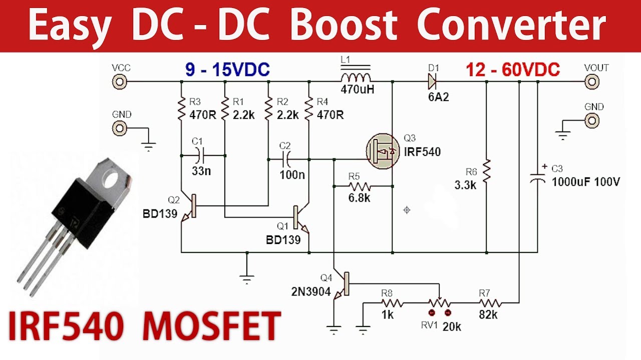
How to make a Simple DC DC Boost Converter Power Supply - YouTube

Dc To Dc Step Up Converter Circuit Diagram | 7petals.in

DC Boost Converter circuit 3.3-5v to 12V-13.8V - Eleccircuit

FEEDBACK Boost converter arduino code

dc to dc converter using 555 timer circuit diagram Archives

Pin on Arduino